Insulating Chilled Water Systems
Aug. 18, 2022
by JM Editors
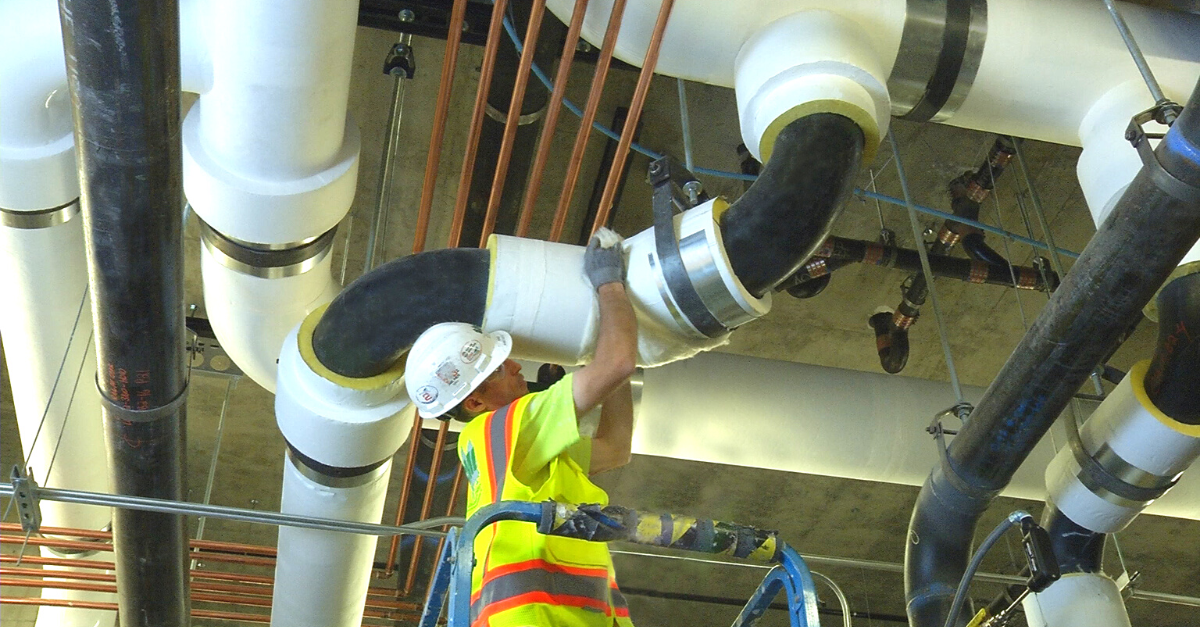
Insulating Chilled Water Systems
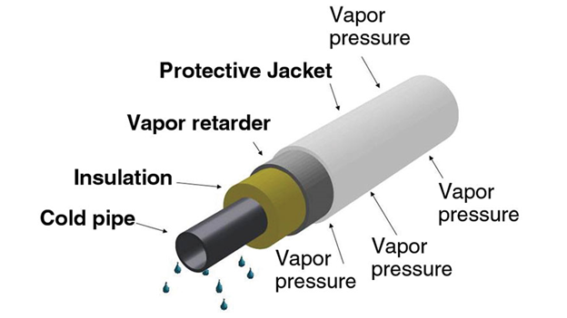
A successful chilled water insulating system properly manages the flow of both heat and moisture. Just like heat wants to flow from high temperature areas to low temperature areas, moisture wants to move from areas of high vapor pressure to low vapor pressure. This tendency is called vapor drive.
Insulation slows the transfer of heat. Its thermal conductivity, or K-value, indicates its ability to conduct heat. Therefore, the lower the K-value, the more effective the insulation is. Likewise, a vapor retarder helps slow the transfer of moisture. Its effectiveness is measured in vapor permanence, or perms, which is the amount of water vapor that can pass through a material over a given period of time. The lower the perms, the greater the material’s ability to limit moisture drive, so a vapor retarder with a perm rating of 0.0 perms would provide undetectable moisture drive when tested. For a chilled water system, the vapor retarder perms rating should be 0.02 or lower.1
An insulation solution in chilled water systems plays a number of roles. It brings down the energy demand on the system by regulating the temperature and making the system more efficient, reducing energy use and cost. Insulation also provides condensation control. Warmer air coming into contact with a chilled pipe will cause condensation, just like a glass of ice water will produce condensation on a hot day.
Why it’s important to minimize condensation
Water is one of the greatest threats to the integrity of any insulation system. Designers of chilled water pipe systems must be particularly careful of this issue because the difference in temperature between the pipes and the ambient air makes these systems more susceptible to condensation than other types of mechanical systems.
While some condensation may not seem like a huge problem, condensation on pipes can lead to complications, including mold growth on pipes and in the surrounding areas; damage to building materials below the pipes; and safety hazards resulting from water dripping on the floor. Moisture can also cause substantial damage to the pipe insulation as well as the pipes themselves. Mold growth caused by moisture can be extremely costly to correct and it's potentially hazardous to building occupants if it goes unchecked. Additionally, in applications where the insulation is left exposed, water stains on the jacketing can damage the appearance of the insulation system.
A chilled water system diagram
1. Specify the right amount of insulation
One of the best ways to prevent condensation in a chilled water pipe system is to make sure the system has enough insulation to keep the surface temperature of the insulation above the dew point. If insulation is not thick enough to avoid the dew point at its surface, condensation will form on the insulation.
It’s important to consider the relative humidity of the environment when selecting your insulation and vapor retarder materials. Locations with higher relative humidity will require more attention; the warmer and moister the location, the more risk a chilled water system faces from ambient conditions. Vapor drive increases as the difference between the pipe system conditions and the ambient conditions increases.
NAIMA recently upgraded its 3E Plus software, which is designed to help users calculate heat losses and to determine surface temperatures on hot and cold piping and equipment. The application uses the heat flow calculation method from ASTM C680, Standard Practices for Determination of Heat Gain or Loss and the Surface Temperature of Insulated Piping on Equipment Systems by the Use of a Computer System. The 3E Plus software can be a helpful tool for determining the correct amount of insulation to use and it’s now available on all types of devices in addition to PCs.
2. Use an appropriate vapor retarder
A vapor retarder is jacketing that’s applied to the outside of the insulation system. It helps protect the efficiency of the system and prevent condensation. Specifying a low-permeance vapor retarder can help disrupt vapor drive through the insulation. Typically, vapor retarders are applied to the insulation at the manufacturing facility (for fiberglass) or the fabrication facility, or in the field (for closed cell foam, like polyisocyanurate).
With all vapor retarders, it is critical to seal all seams with a matching vapor retarder tape and ensure the vapor retarder jacket doesn’t have any punctures or tears in it. If the jacketing system is improperly sealed or it has punctures or tears, the system will not be properly sealed. In this case, vapor drive can occur and lead to condensation, even if there is sufficient insulation thickness to otherwise prevent it. Mastics can also be used in conjunction with jacketing. Mastics can serve as a vapor dam and can also be used to seal seams and punctures.
When considering vapor retarders, there are several options available that suit the requirements of a chilled water insulation system, including: all service jacketing (ASJ); polypropylene coated ASJ that offers superior moisture resistance (like the jacketing on Micro-Lok® Ultra pipe insulation); and polyvinylchloride (PVDC) jackets like Saranex® CX Vapor Retarder Film. The jacketed insulation can also resist temporary exposure to small amounts of liquid water as long as the exposed fiberglass ends have been vapor-sealed.
3. Consider the setting
When designing a chilled water system, make sure the insulation and vapor retarder are appropriate for the setting. For example, in areas with high traffic, protective jacketing should be used to prevent damage to the insulation and vapor retarders. There are several metal and PVC jacketing systems available. Johns Manville Zeston® PVC systems are offered in a variety of colors as well as UV-resistant white.
4. Choose the right products
Johns Manville offers numerous insulation products that are appropriate for chilled water applications.
Fiberglass pipe insulation. Micro-Lok® HP and Micro-Lok® HP Ultra are pre-formed, pre-slit fiberglass pipe insulations with factory-installed vapor retarders. Micro-Lok HP pipe insulation has ASJ with a perm rating of 0.02, while Micro-Lok HP Ultra has poly-coated ASJ with a perm rating of 0.01. These two options are relatively low cost and are widely used among insulation installers so there’s a lot of installation expertise available. Fiberglass insulations like Micro-Lok HP can be used on chilled water systems in exposed, outdoor environments if a metal or PVC jacketing is used with it.
Polyisocyanurate (PIR) foam pipe insulation. TRYMER® 25-50 is a closed cell, rigid pipe insulation with good compressive strength. It is supplied in the form of bunstock for fabrication into pipe shells and other shapes for a variety of thermal insulation applications. The vapor retarder can be applied by the fabricator, so there are numerous vapor retarder options including ASJ, poly-coated ASJ, Foil/Scrim/Kraft (FSK) and PVDC. TRYMER 25-50 is free of chlorofluorocarbons (CFCs) and hydrofluorocarbons (HFCs).
Vapor retarder systems. SARANEX® CX Vapor Retarder Film and Tape are durable, flexible PVDC jacketing materials. These high-performance, cost-effective vapor retarder products help prevent water absorption and resist moisture vapor drive into the insulation, even at elbows and fittings.
Protective jacketing. Zeston PVC products are made from high impact PVC material that’s designed to provide abuse-resistant, vapor retardant protection to insulated pipes. They come in a variety of colors along with UV-resistant white.
Learn more
To learn more about how to specify a chilled water system, watch our popular and informative Insulation Intel® webinar, Insulating Chilled Water Pipe Systems.
You can also check out the Guide to Insulating Chilled Water Piping Systems with Mineral Fiber Pipe Insulation from NAIMA.
1. NAIMA, Guide to Insulating Chilled Water Piping Systems with Mineral Fiber Pipe Insulation 33°F to 60°F (0.5°C to 15.6°C) First Edition, https://insulationinstitute.org/wp-content/uploads/2015/11/CI228.pdf