There are all kinds of noises that can disturb tenants in multi-unit buildings such as office buildings, high-rises, condos and duplexes. Passing cars, ambulances, trains and other tenants can all cause unwanted noise. But another potentially significant source of noise is the noise associated with the building’s pipe systems. This is why it’s important for engineers to keep acoustics in mind when they’re specifying pipe systems for multi-unit buildings.
Engineers may find it helpful to learn more about the existing test methods used to determine the acoustic performance of pipe systems. ASTM International has developed two standard test methods that are relevant for engineers specifying pipe systems for multi-tenant buildings. ASTM International is one of the world's largest international standards developing organizations, creating and publishing standards for materials, products, systems and services.
Mechanical engineers primarily use two test methods to determine the performance of different acoustic systems and to help design insulation or lagging for specific jobs. Those two test methods are ASTM E1222 and ASTM E90, each discussed in detail below. For pipe systems, ASTM E1222 is more relevant because the insulation is tested in a pipe configuration that is more consistent with installation in the field.
ASTM E1222
ASTM E1222: Standard Test Method for Laboratory Measurement of the Insertion Loss of Pipe Lagging Systems determines how effective insulation or lagging is at reducing breakout noise from a pipe. The term insertion loss refers to reducing sound by adding insulation and/or jacketing (lagging) to a pipe or duct system to prevent sound from traveling outward, away from the source of the noise.
During the E1222 test, noise is produced inside a pipe (commonly made of steel) in a reverberation room, which is a room designed to reflect noise equally in all directions. Average sound pressure levels are measured first with sound radiating from the bare pipe and then with sound radiating from the same pipe covered with a lagging system. The insertion loss of the lagging system is the difference in the sound pressure levels measured with sound radiating from the bare and lagged pipe, with an adjustment for changes in room absorption due to the addition of the lagging system.
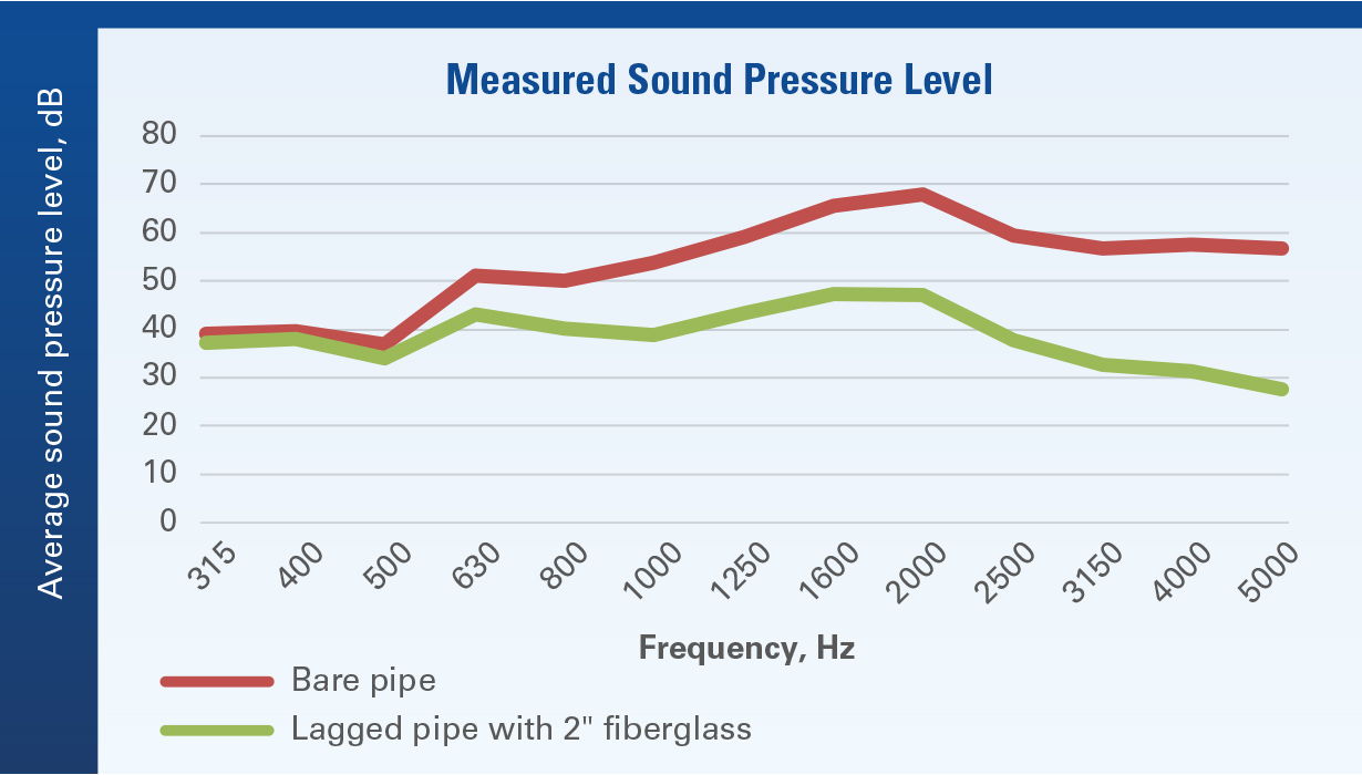
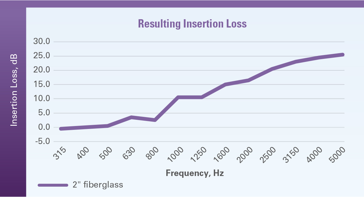
Figure 1 shows an example of raw data collected when testing bare pipe and pipe lagged with 2 inches of Johns Manville Micro-Lok® HP Ultra Pipe Insulation. The higher the pressure level, the higher the noise perceived by our ears. The graph shows that the noise from the bare pipe was between 40 and 65 decibels (dB). When we added the 2 inches of Micro-Lok® HP Ultra fiberglass insulation, the pressure level/noise decreased substantially, especially for frequencies over 1000 Hz. As a rule of thumb, a difference of 10 dB is perceived as half as loud or quiet. From the raw data presented in Figure 1, insertion loss can be calculated, and the resulting graph is shown in Figure 2. This graph shows that 2 inches of fiberglass insulation is effective in reducing noise at frequencies above 1000 Hz. The fiberglass did not significantly contribute to noise reduction at lower frequencies because fiberglass is relatively light and greater mass is needed to reduce lower frequencies.
Figure 1. Measured sound pressure level for bare and lagged pipe.
Figure 2. Resulting insertion loss for pipe lagged with 2 inches of fiberglass insulation.
ASTM E90
Another test that can help engineers specify the right acoustic treatment for pipe scenarios is ASTM E90. This test measures the airborne sound transmission loss of interior and exterior building partitions and elements, such as windows, doors, and roof assemblies. The test results are used to calculate the sound transmission class (STC) and outdoor-indoor transmission class (OITC) ratings of the item tested. According to a sound control guide developed by the North American Insulation Manufacturers Association (NAIMA), STC is a numerical rating of the ability for a wall or floor/ceiling assembly to minimize sound transmission. The higher the STC rating, the better the wall or floor/ceiling assembling can minimize sound transmission. The OITC is a number rating of the sound transmission loss of a constructed assembly, and helps designers determine how effectively their design will protect occupants from sounds generated outside of the building or unit.
ASTM E90 testing is done in a flat configuration, where the assembly under test is installed in an opening of a wall, so it’s not as relevant or applicable for pipe systems. Accordingly, some caution is needed in interpreting E90 results for pipe insulation. In addition, poor installation can reduce acoustic performance by approximately 15-20 points from the laboratory values, according to NAIMA. By definition, pipe system installation will not be flat and results are expected to deviate from those obtained in the lab when running ASTM E90. ASTM E1222 is therefore a more relevant test when it comes to the pipe geometry.
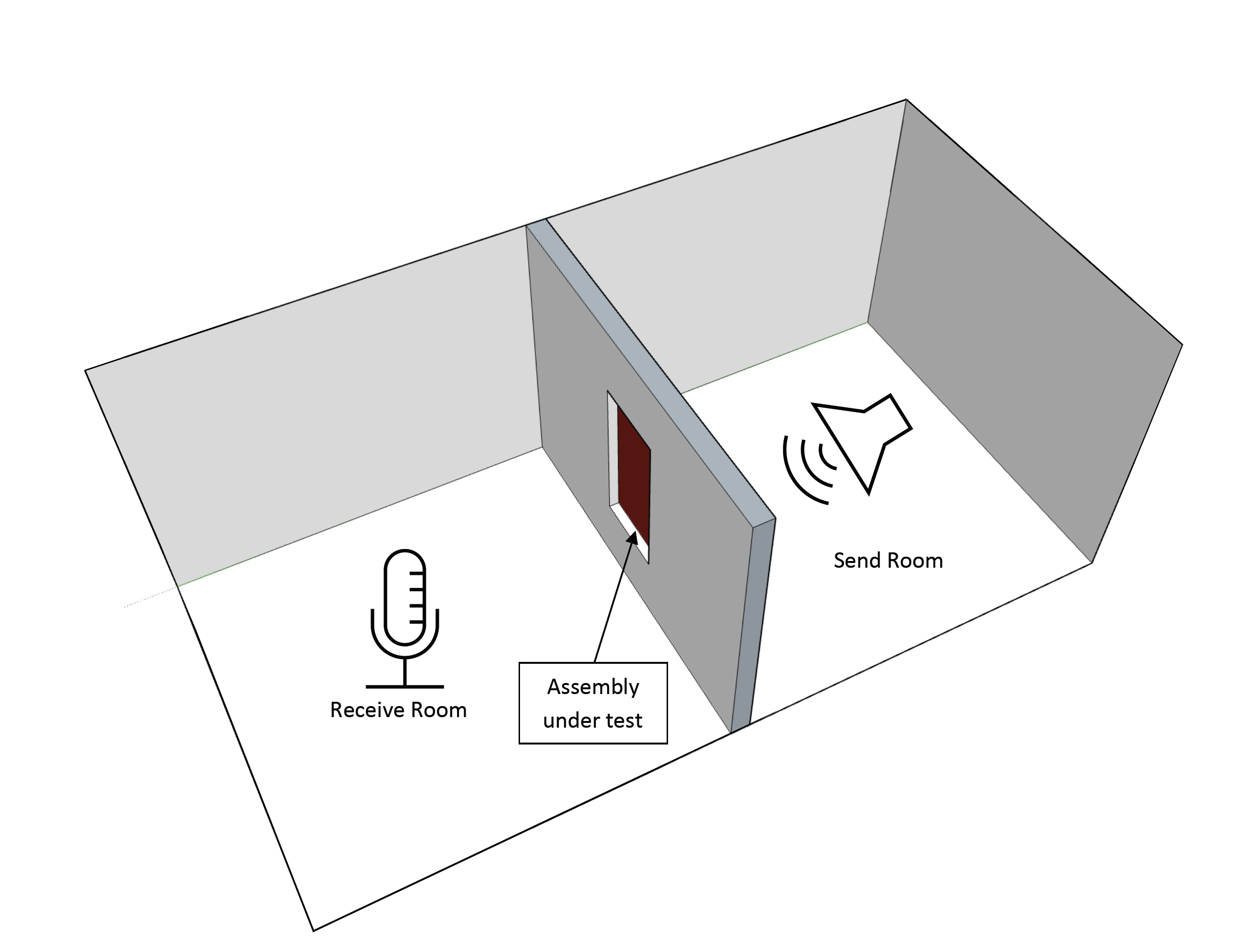
For the ASTM E90 test, two reverberation rooms are set up adjacent to one another with an opening between them. The item to be tested is installed in the opening between the rooms. Noise is generated in one room and received in the second room. The test measures the sound transmission loss between the sending and receiving rooms. An example layout of this testing is shown in Figure 3.
Figure 3. Schematic of the room set up for ASTM E90 testing.
Exploring different solution options
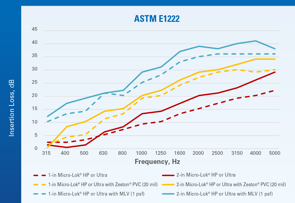
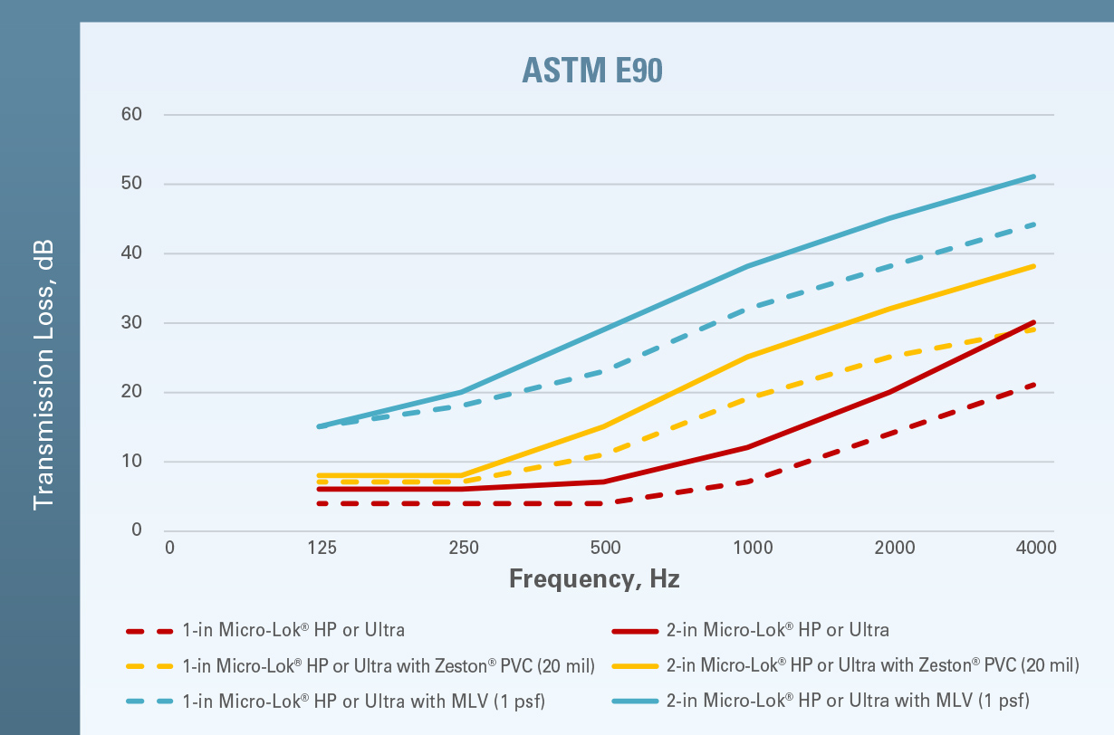
Different combinations of materials will give you different results. Figure 4, Figure 5 and Figure 6 show the performance of lagging assemblies using 1-inch and 2-inch Micro-Lok® HP or Micro-Lok® HP Ultra fiberglass insulation as a base on 12-inch pipe. Zeston® PVC and JM Mass-Loaded Vinyl jacketing are also shown. The two figures also show that the addition of mass-loaded vinyl further improves the performance of the lagging systems. Please note the performance below 1000 Hz. Lower frequency noises in pipes may originate from pumps, compressors, flow noise, various bending modes of the pipes or vibrations transferred structurally. As can be seen in Figure 4, lagging systems with JM Mass-Loaded Vinyl can provide noise reduction between 10 and 40 dB depending on the frequency, which can provide substantial mitigation of noise. You’ll notice that the y-axis shows numbers below zero. This is because some lagging systems can actually add to the noise. This may happen for a variety of reasons and it is usually only an issue at lower frequencies. Similar performance is seen in the ASTM E90 data shown in Figure 5.
Figure 4. Results for ASTM E1222 using Micro-Lok HP or Micro-Lok HP Ultra fiberglass insulation, Zeston® PVC jacketing and JM Mass-Loaded Vinyl as lagging options.
Figure 5. Results for ASTM E90 testing using Micro-Lok® HP Ultra fiberglass, JM Zeston® PVC, and JM Mass-Loaded Vinyl as lagging options. Caution is needed in interpreting E90 results for pipe insulation.
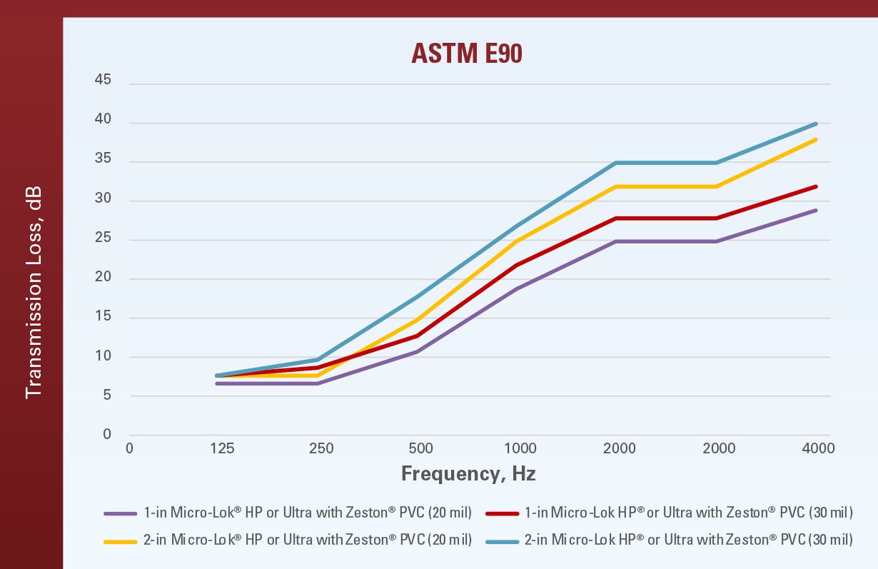
Figure 6. 30 mil Zeston® PVC jacketing provides increased performance with regard to transmission loss. Caution is needed in interpreting E90 results for pipe insulation.
Learn more
There are multiple options for pipe insulation solutions with varying degrees of complexity and performance. Depending on the situation, budget and space constraints, it’s possible design a system to help mitigate noise and keep residents happy (and quiet). To read JM’s guidance on designing with acoustics in mind, visit:
https://www.jm.com/en/blog/2022/march/keeping-tenants-happy-by-designing-pipe-systems-with-acoustics-i/
To learn more about JM solutions that can help you address acoustics issues, visit:
https://www.jm.com/en/mechanical/acoustics/